Speaker
Description
First results of KIT 3D USCT III system crosstalk analysis
Motivation
The KIT 3D USCT III system is built around the idea of SAFT. One ultrasound transducer emits a signal while thousands of others receive - Leading to a system with large number of parallel channels consisting of cables, traces, and connectors. SAFT requires unfocused small transducers necessitating a multi-stage amplification chain, sensitive to crosstalk. As we have to maintain the integrity and fidelity of the signals over the long path until digitization, crosstalk is the natural enemy of this system’s approach.
Method
While electrical crosstalk analysis can be done on a component level, the complete analysis would be a long endeavour and would not represent the final system-level situation. This also neglects non-electrical effects like mechanical propagation. Traditional methods for system-level signal analysis are not applicable, as they require positive SNR. We propose a higher-level crosstalk analysis method, inspired by SAFT, which creates the required SNR by projecting the signals into a 3D spatial domain. We can target emission and receiving paths independently, representing the complete chain from excitation over ultrasound to data.
Results
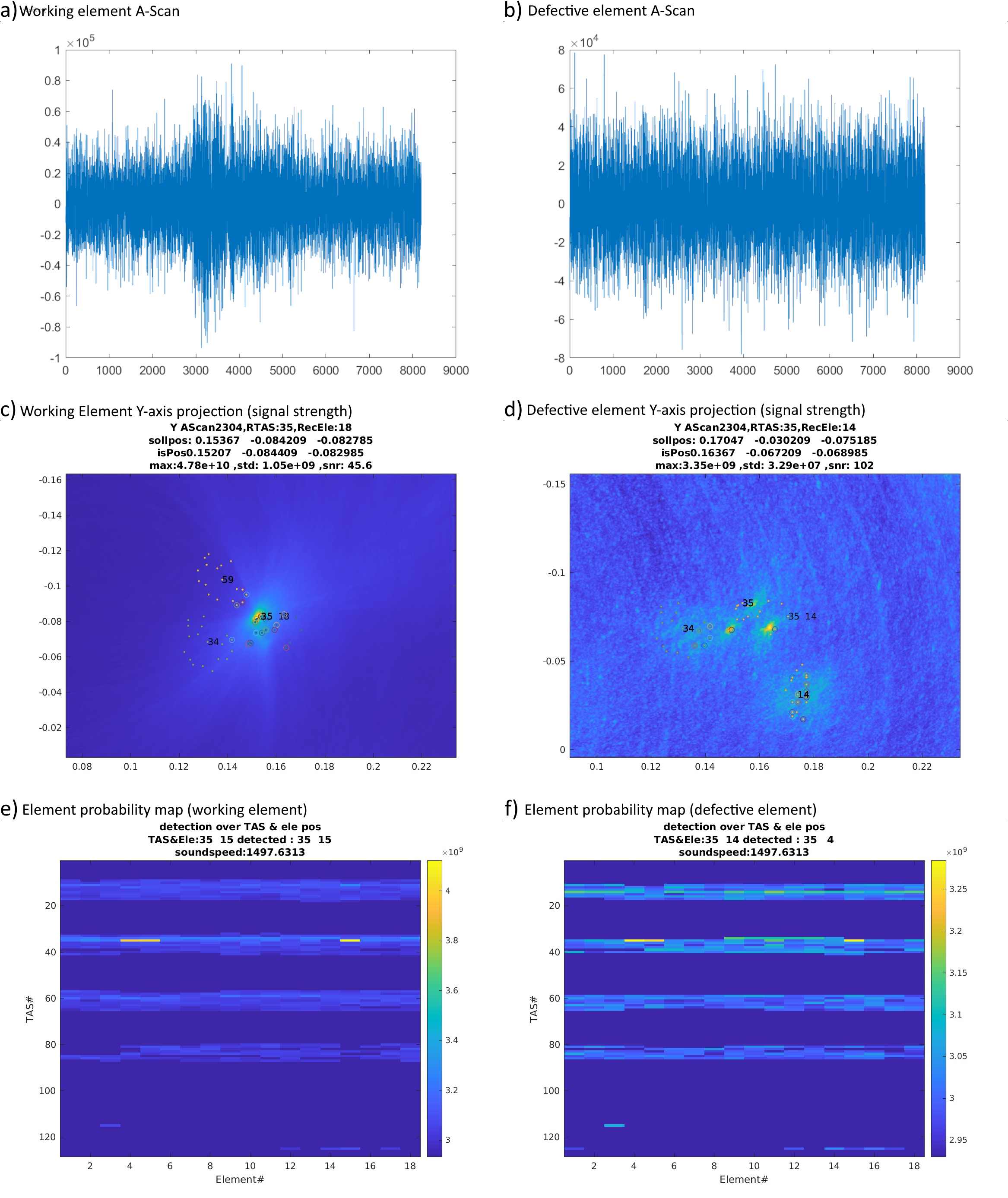
Our method applied to a typical USCT calibration measurement as emitter detection is shown below. On the left, we can see a good element with a defined emission; On the right, the element is dominated by crosstalk (dead or damaged element) and is visible and can be quantified.
Summary
This in-system method is a fast and complete analysis without the need for extra hardware and manual work steps. It shows potential for hardware debugging by identifying crosstalk paths and components. Digital effects and cabling misconfigurations can also be identified as well. We quantify the worst-case crosstalk of -9dB compared to a typical working signal chain.


